Emerald Phono Stage
Two stage op amp design, switchable MM/MC gain and cartridge loading.
A phono stage for either moving magnet or moving coil cartridges with the following features:
- Switch between 40 dB and 60 dB gain.
- Switch between 47.5k and 100 ohm input load.
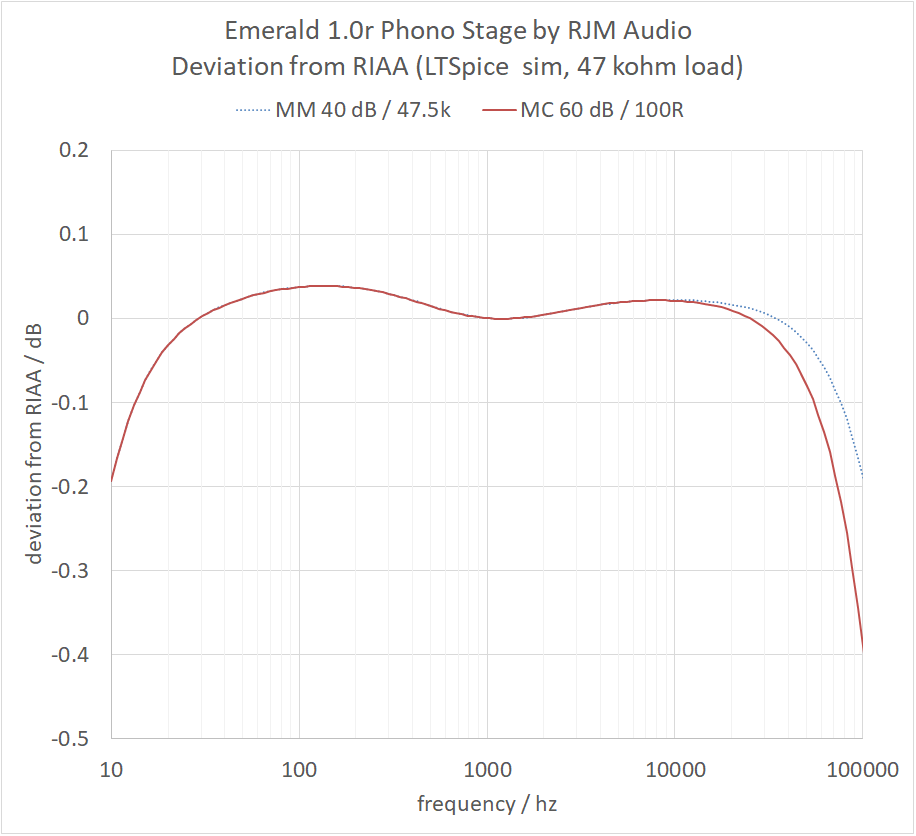
- Extremely accurate RIAA equalization.
- Consistent performance in both gain modes.
For an op amp phono stage, every design decision implies a compromise of some sort. The Emerald takes everything I've learnt so far with the VSPS (MM only) and Phonoclone (MC only) and starts again from the ground up. This time, the aim was to create a circuit that works with all kinds of phono cartridges, low gain and high gain, moving magnet and moving coil.
Most phono stages traditionally start with a 40 dB equalization amplifier for MM use and add a separate 20 dB flat gain stage at the input to bring the total gain to 60 dB needed with MC cartridges. The flat gain stage can even be a separate active component, called an MC head amplifier, or pre-preamplifier. Needless to say the sonic and noise characteristics of the circuit with and without the extra input stage can be drastically different.
The Emerald design takes a different strategy. It's a native two-stage equalization amplifier which operates at two fixed gain settings. The active circuit is the same for either MM or MC cartridges and the performance is consistent.
At first glance the Emerald might seem like the ultimate cop out, trading performance for convenience. This view does the circuit an injustice however. It is a very good MM amplifier, far superior to the VSPS in every way. As an MC amplifier it is sonically consistent with the Phonoclone - they are nearly identical but for the inverting vs. noninverting op amp configuration and the details of the treble cut filter - while offering the versatility of also being an MM phono stage when needed.
The Amplifier Circuit
The Emerald circuit schematic is shown below. The jumper JP1 has two switches. J1-1 connects R2 into the input load, reducing the input impedance from 47.5k (R1) to 100 ohms. J1-2 connects R3 to the inverting input, increasing the gain of IC1. IC1 and IC2 are OPA27. Any audio op amp can be used for the MM configuration, but bipolar input types with low offset voltage will be needed for the MC setup. R6 and C1 form the treble cut RIAA filter, while C2, R7, R8, and R9 provide the rest of the RIAA frequency shaping. The output is passed through a damping resistor R10 and the output coupling capacitor C3 which removes the DC offset voltage.

The Phonoclone is a similar two-stage MC phono preamp, but with both op amps configured as inverting amplifiers and zero ohm input impedance the circuit cannot be modified to work with MM cartridges. The Emerald makes the required change to non-inverting amplifiers and variable input impedance, but that now means the amplifier gain cannot be reduced below unity. Like the VSPS, the high frequency response would cease to follow the RIAA curve when the filter network can no longer apply the necessary attenuation. In the Emerald this problem can be neatly solved because unlike the single stage VSPS we have two gain stages and this provides a buffered interstage area into which a passive low pass filter can be safely inserted. This hybrid (active/passive) approach to the equalization brings a number of benefits compared to a full passive approach. Most importantly it allows about 20 dB more voltage gain to be obtained from the same active amplification devices.
As always with multistage phono preamplifier design, there is a balance to be struck between noise and voltage headroom, or even between low noise at low frequency or low noise at high frequency. In the Emerald I have tried to split the difference, taking a middle road wherever possible. Implementing a passive low pass filter in the interstage does compromise the treble noise, but as configured this is only in the MM configuration and only at the highest audible frequencies. This is in return for tangible benefits in signal headroom and high frequency RIAA accuracy.
The resistor values are not common, but are standard 1% values and available at Mouser, etc. As seen in the simulation, the RIAA response of the circuit is accurate to within 0.1 dB provided the components used in the RIAA network are 1% tolerance or better.
Power Supply
A 25 VA toroidal tranformer with two 12 VAC secondaries is connected to two bridge rectifiers to generate the V++ and V-- voltage rails that power the circuit board. The filter capacitors are on the main circuit board, next to the voltage regulation circuitry. No capacitors are used in the power supply. The AC line components are not shown in detail. The power supply chassis is normally connected to earth for safety, and the AC line is fused with a 1 A slow-blow fuse. The power supply can be in the same chassis as the amplifier circuit.

The power supply.
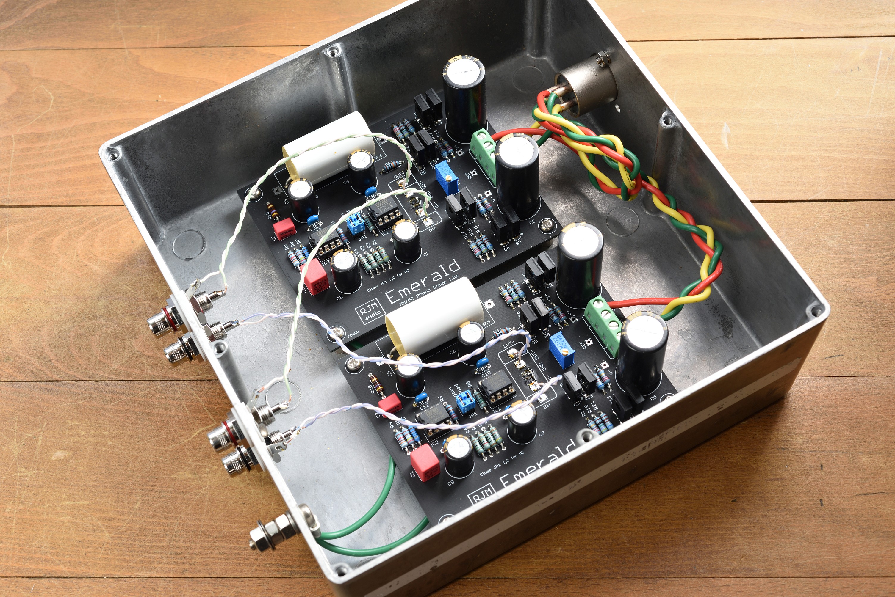
The rectified DC from this power supply, V++, V--, then goes to filter capacitors and voltage reguators on the main board, to deliver ±12 V, V+, V- to the op amp ICs.The Circuit Board
Dual mono, dual sided circuit boards have been designed for this project. S-Reg voltage regulation is included on the boards, which are powered by unregulated supply voltages V++ = 18 V and V-- = -18 V, just the same as the VSPS and Phonoclone projects.

The Emerald circuit board, one channel shown.
Design Manual / Schematic Files
Construction Notes
The voltage regulation and filtering is placed on the same board as the phono circuit. The power transformer and rectifier diodes are typically in a separate chassis connected by an umbilical cable.
rjm003.geo at yahoo.com